

Step 1 – Learn Basic Circuit Symbols
Before you start drawing, it’s important to understand the standard BIS/IEC electrical symbols used in diagrams. These help anyone reading your circuit know exactly what each part represents.
Common Symbols and Their Meanings
| Component | Symbol Description |
| Wire | A straight line representing a conducting path for current. |
| Electric Cell / Battery | One or more pairs of long and short lines; the longer line shows the positive terminal. |
| Resistor | A zigzag or rectangular box symbol showing resistance in the circuit. |
| Light Bulb (Lamp) | A circle with a filament (cross or loop) inside. |
| Switch (Open / Closed) | Open: a gap in the line; Closed: a line connecting both ends. |
| LED (Light Emitting Diode) | A diode triangle with arrows pointing outward, showing light emission. |
| Ground | A set of three lines decreasing in size, showing the connection to earth. |
Tip Box: Use standard IEC or BIS symbols for clarity and accuracy. Avoid inventing or modifying shapes.
Step 2 – Plan the Layout of Your Circuit
Now that you know your symbols, plan your circuit before you draw. This will help you maintain a clean, logical layout.
Arrange Components Logically
- Place the power source (battery or cell) on the left side.
- Let the current flow from left to right.
- Arrange components like switches, bulbs, and resistors in a line or neat pattern.
- Keep equal spacing between symbols so the circuit looks balanced.
Follow Neatness Rules
- Use only straight horizontal and vertical lines.
- Avoid diagonal or overlapping wires.
- Keep connections at right angles for a tidy look.
Step 3 – Draw the Components and Connect Them
Once your layout is clear, start drawing the actual circuit diagram.
Place Symbols First
Begin by placing the battery on the left, then add other symbols like a switch, resistor, or bulb in sequence. This makes it easy to connect them later.
Connect with Straight Lines
- Use a ruler for perfect straight lines.
- Connect the symbols with wires meeting at right angles.
- Avoid unnecessary bends or curves.
Check for a Closed Loop
- Every circuit should form a complete path — from the positive terminal to the negative terminal of the battery.
- A closed circuit allows current to flow and light up the bulb.
- An open circuit has a gap (open switch), so the current cannot flow.
Step 4 – Label All Components
Labelling makes your diagram clear and easy to understand.
Add Component Names and Values
- Label each part: battery, switch, bulb, resistor, etc.
- Include values where needed, such as voltage (V), resistance (Ω), or current (A).
Tip Box: Always use SI units when labelling your components.
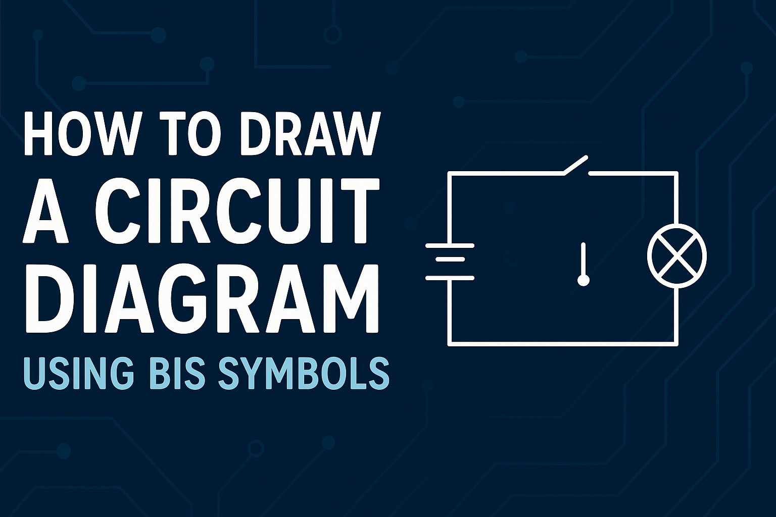
Example – Simple Circuit with Battery, Switch, and Bulb
Let’s put it all together!
Step-by-Step Example
- Draw the battery symbol on the left.
- Add a switch in the middle.
- Place the bulb symbol on the right.
- Connect all with straight lines to form a closed loop.
- Label each component clearly.
When the switch is closed, current flows from the positive terminal, through the bulb, and back to the negative terminal. The bulb glows, indicating a closed circuit.
If the switch is open, the circuit breaks and the bulb stays off.
Key Rules and Best Practices
To make your circuit diagrams both clear and correct, follow these golden rules:
- Never use curved or slanted lines.
2. Always close the circuit loop.
3. Keep your layout simple and logical.
4. Use correct component symbols.
5. Maintain equal spacing between parts.
Tip Box: Neatness and clarity make your circuit easy to read and understand.
Common Mistakes to Avoid
Even experienced students make small errors while drawing circuits. Here’s what to watch out for:
- Changing the shape of standard symbols (for example, drawing a triangle for a bulb).
2. Disconnected wires or crossed lines without proper junctions.
3. Forgetting to label symbols with their names or values.
4. Using uneven spacing or slanted lines that make the circuit look messy.
Real-Life Applications
Circuit diagrams are not just classroom exercises — they’re used everywhere!
- In school labs: To connect components safely during experiments (like lighting a bulb using a cell and switch).
- In electronics: To plan circuits for radios, fans, or lights.
- In engineering projects: To design complex systems with resistors, capacitors, and transistors.
- In homes: For domestic wiring diagrams that show how switches, fans, and sockets are connected.
Learning how to read and draw circuit diagrams is the first step towards understanding how electrical systems work in the real world.
Summary
Drawing a circuit diagram is not about art — it’s about clarity. Using BIS symbols ensures everyone understands the components and connections in your circuit.
A well-drawn diagram shows:
- Where current flows (input → process → output).
- How components connect in sequence.
- Which parts control or use electricity.
With these steps, you’ll be able to draw any electrical circuit diagram — from a simple bulb setup to a complex multi-resistor network — neatly and confidently.
FAQs
1. Why do we use standard symbols in circuit diagrams?
Standard BIS or IEC symbols help ensure that everyone — from students to engineers — can read and understand the circuit easily.
2. What are the basic rules of drawing a circuit diagram?
Use straight lines, standard symbols, neat labels, and ensure the circuit is closed. Avoid curves, overlaps, or uneven spacing.
3. How do you show current flow direction?
Use arrows to indicate the current moving from the positive terminal of the battery to the negative terminal.
4. What is the difference between open and closed circuits?
In an open circuit, there’s a break or gap (like an open switch), so current doesn’t flow. In a closed circuit, current flows freely and the bulb lights up.
5. Which software can be used to draw circuit diagrams?
You can use tools like Fritzing, Tinkercad Circuits, EdrawMax, or even Microsoft Visio to create neat digital circuit diagrams.